SD-WAN Lab in FortiManager 7.6
With FortiOS 7.6 reaching maturity soon, it was time to upgrade my SD-WAN lab of FortiGate VMs. And with Broadcom doing a spectacular job of killing off VMware (I was a VMUG member enjoying my ESXi license, I’m allowed to rant), I also rebuilt my server to run ProxMox. With all these new events, it was time to write up how I rebuilt everything!
WAN Emulator
In my earlier lab, I used WANem to emulate my WAN and inject latency and packet loss. But I’ve played with tcgui in other labs and wanted to try it out. I hands down recommend it for your lab too! Before, I had a separate VM to serve DHCP addresses to my WANs but now I’m able to combine that functionality with WAN emulation on one Linux VM running both tcgui and a DHCP server.
Setup the VM Networking
I began by deploying a Ubuntu Linux VM with multiple NICs, one in each network WAN. These VLANs mostly reside within my ProxMox server allowing VM to VM connectivity. The only routable VLAN one is my WAN Uplink network so that my lab can go through my hardware FortiGate and out to the Internet. Here are the NICs that I setup on my WAN emulator with dummy public IP addresses (that get NAT’d when they leave the lab):
Infrastructure/Management (VLAN A)
Hub WAN1 (VLAN B) - 100.67.23.0/24
Hub WAN2 (VLAN C) - 200.91.78.0/24
Spoke WAN1 (VLAN D) - 76.54.83.0/24
Spoke WAN2 (VLAN E) - 128.64.32.0/24
WAN Uplink (VLAN F) - 192.168.99.0/24
I then modified routing to use the default route of the WAN Uplink:
sudo vim /etc/netplan/50-cloud-init.yaml
network:
version: 2
ethernets:
ens18:
addresses:
- "192.168.5.102/24"
ens19:
addresses:
- "100.67.23.1/24"
ens20:
addresses:
- "200.91.78.1/24"
ens21:
addresses:
- "76.54.83.1/24"
ens22:
addresses:
- "128.64.32.1/24"
ens23:
addresses:
- "192.168.99.2/24"
routes:
- to: "default"
via: "192.168.99.1"
And then I confirm the routes in the routing table:
wanemulator@wanemulator:~$ ip route
default via 192.168.99.1 dev ens23 proto static
76.54.83.0/24 dev ens21 proto kernel scope link src 76.54.83.1
100.67.23.0/24 dev ens19 proto kernel scope link src 100.67.23.1
128.64.32.0/24 dev ens22 proto kernel scope link src 128.64.32.1
192.168.5.0/24 dev ens18 proto kernel scope link src 192.168.5.102
192.168.99.0/24 dev ens23 proto kernel scope link src 192.168.99.2
200.91.78.0/24 dev ens20 proto kernel scope link src 200.91.78.1
Now I need to modify a few things to allow traffic to route between NICs:
wanemulator@wanemulator:~$ sudo vim /etc/sysctl.conf
Uncomment this line by removing the #: net.ipv4.ip_forward=1
wanemulator@wanemulator:~$ sudo iptables -A FORWARD -i ens19 -j ACCEPT
wanemulator@wanemulator:~$ sudo iptables -A FORWARD -i ens20 -j ACCEPT
wanemulator@wanemulator:~$ sudo iptables -A FORWARD -i ens21 -j ACCEPT
wanemulator@wanemulator:~$ sudo iptables -A FORWARD -i ens22 -j ACCEPT
wanemulator@wanemulator:~$ sudo iptables -A FORWARD -i ens23 -j ACCEPT
wanemulator@wanemulator:~$ sudo apt install iptables-persistent
And save your rules to the file.
Install tcgui
We’ll install tcgui from github and configure it to run at startup via a cron job:
sudo apt install git iproute2 python3-flask
git clone https://github.com/tum-lkn/tcgui.git
Add the Python script to cron to run at reboot:
sudo crontab -e
@reboot python3 /home/wanemulator/tcgui/main.py --ip a.b.c.d --port 5000 &
After reboot, confirm can reach tcgui at http://a.b.c.d:5000/

Install DHCP Server
I setup DHCP for my Spoke WAN interfaces to receive IP addresses:
sudo apt install isc-dhcp-server
sudo vim /etc/dhcp/dhcpd.conf
option fmg code 240 = ip-address;
subnet 76.54.83.0 netmask 255.255.255.0 {
range 76.54.83.10 76.54.83.254;
option routers 76.54.83.1;
option domain-name-servers 8.8.8.8;
option subnet-mask 255.255.255.0;
option broadcast-address 76.54.83.255;
option fmg 192.168.5.105;
}
subnet 128.64.32.0 netmask 255.255.255.0 {
range 128.64.32.10 128.64.32.254;
option routers 128.64.32.1;
option domain-name-servers 8.8.8.8;
option subnet-mask 255.255.255.0;
option broadcast-address 128.64.32.255;
option fmg 192.168.5.105;
}
sudo vim /etc/default/isc-dhcp-server
INTERFACESv4="ens21 ens22"
sudo service isc-dhcp-server restart
sudo service isc-dhcp-server status
Build FortiGate VMs
Now that we have our WAN Emulator built and running, it’s time to build our FortiGate VMs. I used Templates in ProxMox to speed up deploying my Hubs and Spokes since they have similar network connectivity:

Since I’m new to ProxMox, I used this guide for deploying FortiGates and it's very similar to FortiManager, FortiAnallyzer, etc.: https://fortinetweb.s3.amazonaws.com/docs.fortinet.com/v2/attachments/b9537e79-a8f3-11ef-a705-1222899fa4e9/Fortinet-7.6-Proxmox_Administration_Guide.pdf
First, I create the VM with no disk (click the trash can next to scsi0) and using the system requirements specified in deployment docs. I deployed my FortiGate VMs with 4 vCPU and 4GB RAM.
Next, if this is our first time importing a qcow2 image we create a directory to store qcow2 images on the ProxMox hypervisor:
root@proxmox:~# mkdir /var/lib/vz/template/qcow
From my computer, I SCP the image to ProxMox:
computer$ scp fmg.qcow2 root@192.168.5.10:/var/lib/vz/template/qcow/fgt-7.6.4.qcow2
Now, I'll import the image to my VM:
root@proxmox:~# qm importdisk <VM ID> <qcow2 image> <storage name>
root@proxmox:~# qm importdisk 101 /var/lib/vz/template/qcow/fmg-7.6.4.qcow2 ssd_raid5
I edit the VM Hardware > select the Unused Disk 0 > and just hit OK to complete the map.
Then I add an additional 32GB log disk based upon on the deployment guide.
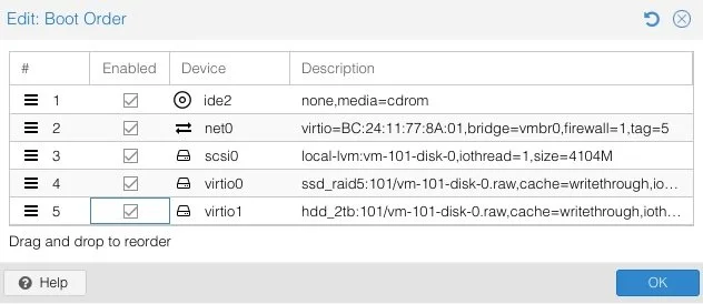
Lastly, I update the Boot Order under Options by checking the new scsi0 disk containing the qcow2 image:
I setup each of my FortiGate VMs with the following networking:
port1 - Management (VLAN A, this has a DHCP server on the network with Option 240 for ZTP)
port2 - Spoke WAN1 (VLAN D, same as WAN Emulator) - 76.54.83.0/24
port3 - Spoke WAN2 (VLAN E, same as WAN Emulator) - 128.64.32.0/24
ports4, 5, 6 - various LAN networks on various VLANs; each Spoke has its own set of VLANs
SD-WAN Overlay Template Wizard
Starting with a fresh FortiManager 7.6 deployment, I created Device Groups for my Hubs and for my Spokes. I then added my 2 Hubs to FortiManager and navigated to the SD-WAN Overlay Template Wizard under FortiManager > Device Manager > Provisioning Templates > SD-WAN Overlay (it might be hidden under Feature Visibility):
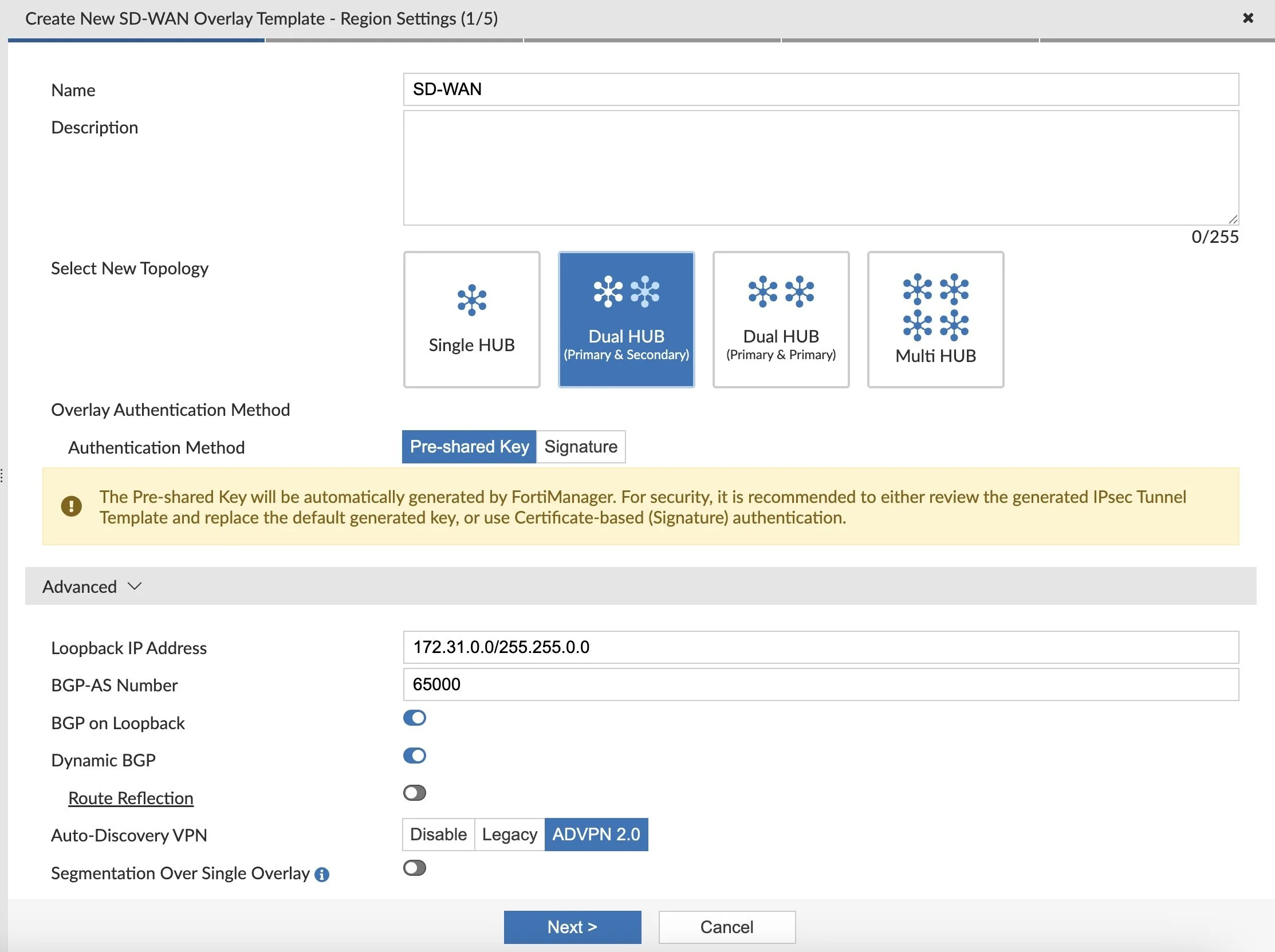
I changed the Loopback Subnet above to be something I wanted to use, but left the defaults as well as ADVPN 2.0 enabled.

I left Branch ID Assignment off above because I like to make my Branch IDs line up with other Metadata Variables values for my router IDs, LAN subnets, etc.

I left Network Advertisement as Connected so I can add Network Statements in my BGP Templates later...

Under Advanced, I specify the RM-VPN-Priority Route-Map to map the Priorities of Branch/Spoke VPN BGP updates. I do this because we tie our SD-WAN SLA health-checks into our BGP advertisements so that Hub to Spoke return traffic takes the same path it originated on. You can read more about that in a separate blog post.

I specify route-map out as 9999 by default, but if my SLA health-check to my Hubs is indeed healthy I set the Priority to 1 on VPN1, 2 for VPN2, etc. This way when the Hub receives any routes from my Spokes, it returns on the path with the lowest Priority (i.e. 1 via VPN1, then 2 via VPN2, then 3 for VPN3, then…. until we give up and take any path back via 9999).

I create an empty SD-WAN Template above so it will add my Overlay interfaces, zones, and tie our BGP neighbors to our health-checks. Lastly, I hit Finish and my SD-WAN Overlay Template along with nested Templates is created:

Metadata Variables
I like to use Metadata Variables for my various LAN networks at each Spoke, as well as other attributes I reference in my templates:
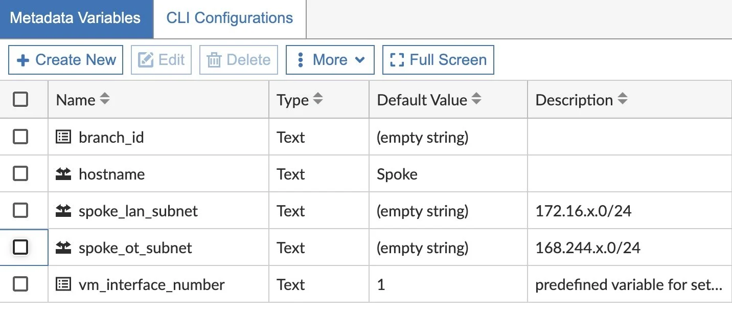
In my BGP Template, I’ll reference this variable, giving it a unique value for each device that receives it.
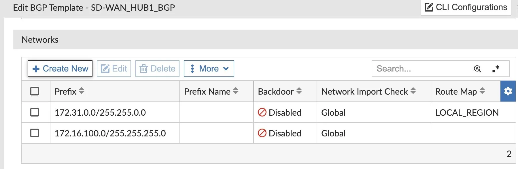
BGP Templates
The SD-WAN Overlay Template Wizard created my BGP Templates, but now I’m ready to add my Network Statements to advertise certain networks. My Hubs are simple, so I hard-code those Network Statements:
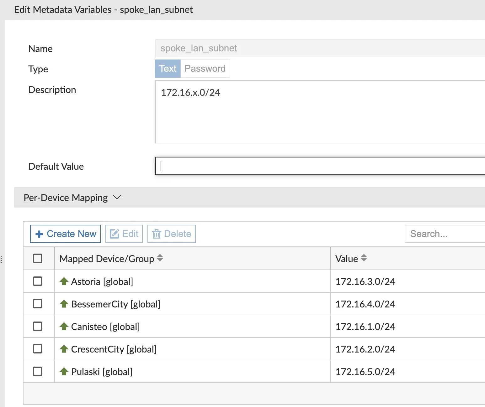
My Spokes use those Metadata Variables so that they can be more modular and reusable:

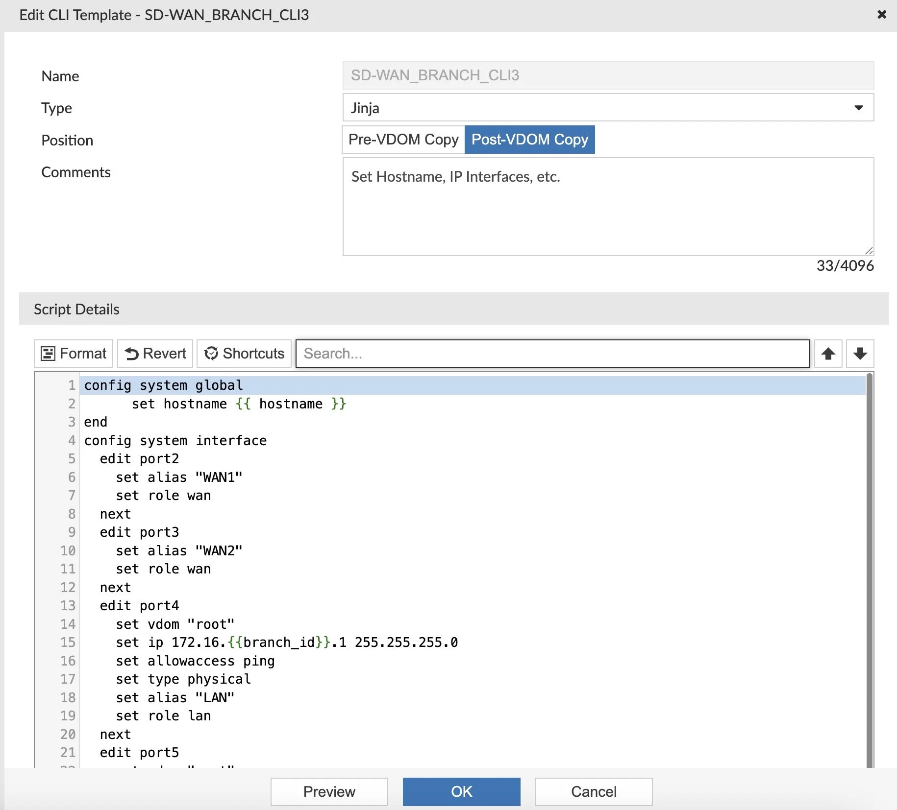
Create Another CLI Template
The SD-WAN Overlay Template Wizard creates a few CLI Templates, but I needed another one to setup “allowaccess” and my hostname and so on. It’s a nice catch-all to set a lot of random settings on my Spokes:
Create Static Route Template
I like using Static Route Templates on my Spokes to standardize my config. Plus it’s best practice to add default routes for our SD-WAN Zones since the magic of SD-WAN requires the route already be in the routing table.

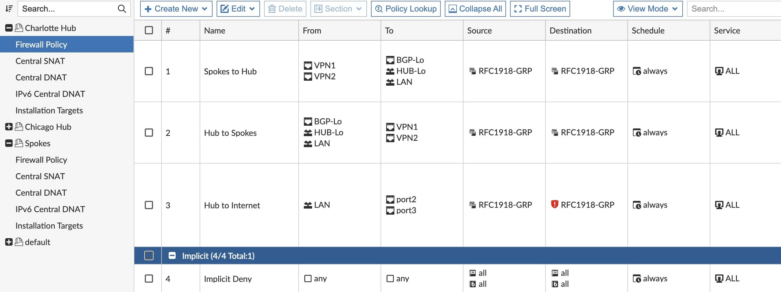
Firewall Policies
In order for our VPN tunnels to come up and traffic to flow, we need to create a few Hub Policy Packages and a Spoke Policy Package. At a minimum, we need inbound access on the VPN tunnels, outbound back to the Spokes and then Hub access to the Internet. After that baseline, we can build upon it.
And likewise on our Spokes:

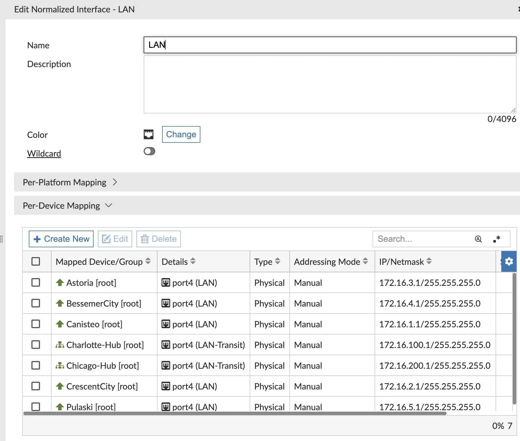
One step I glossed over in the Firewall Policy rules was the need to map our interfaces to Normalized Interfaces. It allows us to reuse our Policy Packages on multiple devices. This says port3 on this FortiGate maps to LAN, which maps to port20 on that FortiGate. In our Spokes Policy Package, we create a Normalized Interface for LAN and map it per device:
At this point all the configuration is ready and we just need to begin adding our Spokes. We’ll add our first as an online, accessible FortiGate and then the remaining as Device Blueprints for ZTP.
Adding Spokes
I added my first Spoke manually via FortiManager > Devices Manager > Add Device > Discover Device.
In that wizard, I added that first Spoke to the Spokes Device Group so that the Provisioning Template Group and Policy Package get applied automatically. With the new FortiGate in FortiManager, I click the Install Wizard and push the config to the first Spoke (first Device Settings so it creates my VPN interfaces, then Policy Package for my firewall rules).
The next Spokes will be deployed using ZTP and Device Blueprints. To do this I click the down-arrow next to Add Device and select Device Blueprint. I created a new one for the Device Model(s) I have in use and select the appropriate Device Group, Policy Package, etc.:
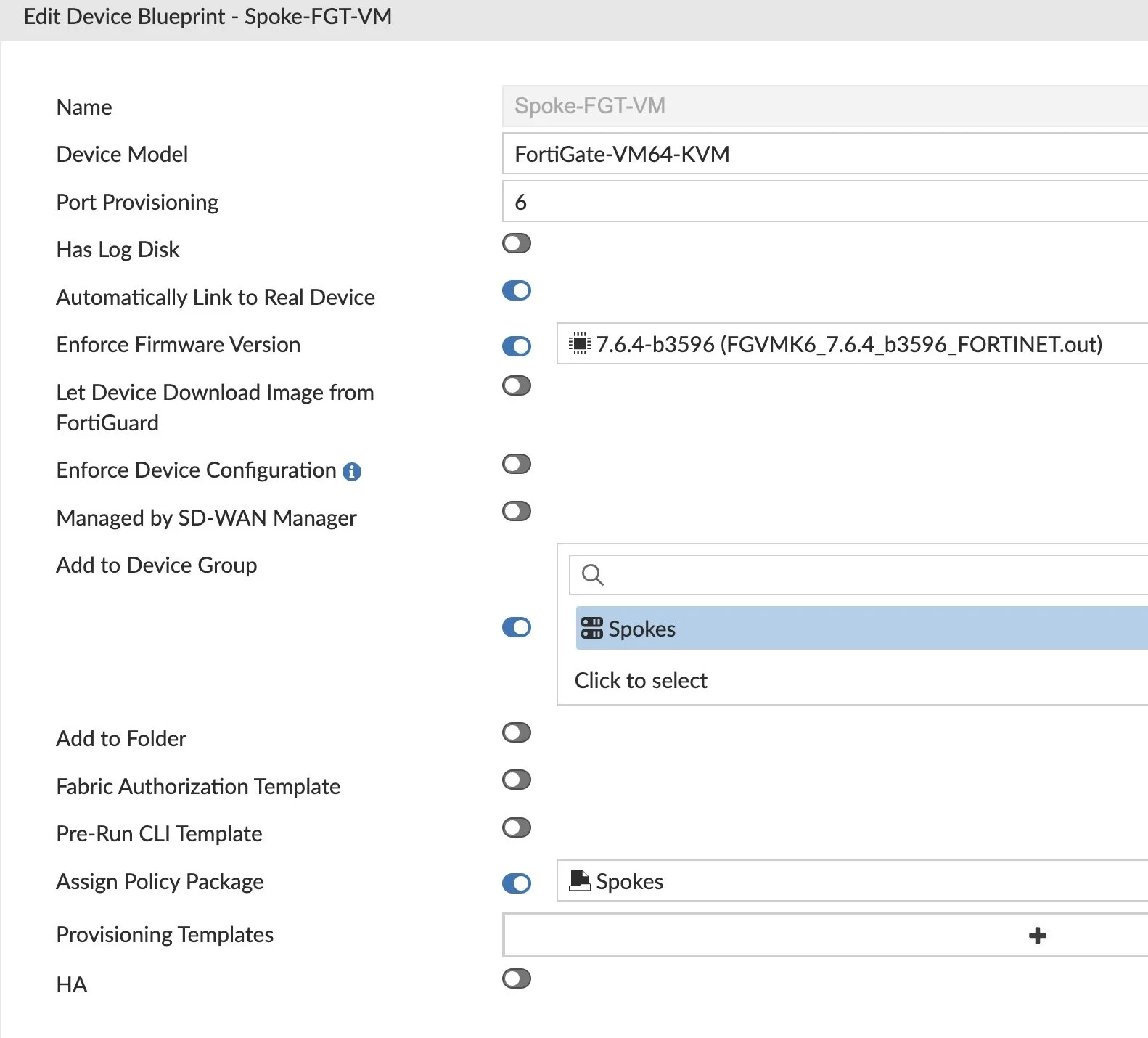
You do NOT need to assign the Provisioning Template Group in the Device Blueprint. By selecting the ‘Spokes’ as Device Group, it will get applied to the model devices as ‘Spokes’ device group is an Installation Target.
I repeat creating more Device Blueprints for remaining Models and Device Groups.
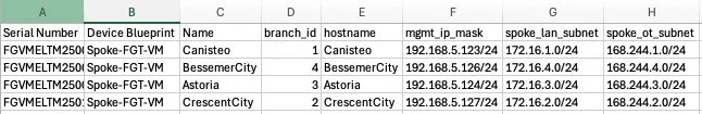
I make a CSV to be used to create the Spoke Model Devices. This file will provide the Spoke FortiGate serial numbers, the Device Blueprint name, device name, number of VM interfaces, and define all Metadata Variables. With this method multiple model devices can be created at one time.
To add these Model Devices, I click on Device Manager > Device & Groups > Add Device > Device Blueprint. I click the Device Blueprint and Generate CSV, then I fill in the fields in the CSV (serial number, Metadata Variables, etc.):
Now we’re ready to import! Under Device Manager, click the ‘Add Device’ button and click ‘Import Model Devices from CSV File’.
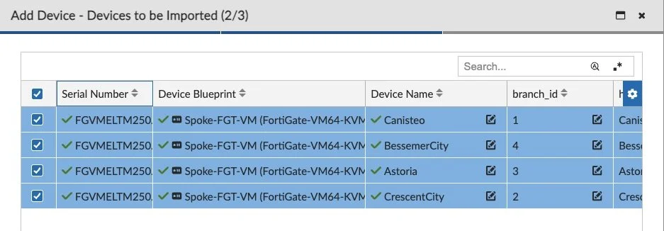
I click Finish and we'll see your new Model Devices waiting for ZTP:

Now I “Install Device Settings” and confirm it was successful. This creates the interfaces, VPN tunnels, routing, etc.
Next, I confirm my Normalized Interfaces (i.e. for LAN, etc.) are mapped correctly under my Device > Network > Interfaces and look at the Normalized Interface column. To map, I right-click that column and Edit Interface Mapping.
Lastly, I “Install Policy Package” to apply my Firewall Policy and confirm it was successful.
At this point my Model Devices are configured and ready. Let’s ZTP them!
For my lab, I'm using the OOB Management network for everything and needed to add Option 240 = FortiManager’s IP address to that network since port1 on the Spoke FortiGates connects to that OOB Management and has DHCP enabled by default. Option 240 tells the FortiGate which IP address to use for FortiManager when it registers.
After logging into the new FortiGate VM and licensing it for FortiFlex, I factory-reset it while keeping the vm license.

Once the FortiGate reboots I can see it Auto-linking and then coming online with its new config! I can also view Systems Settings > Task Monitor to see the full installation log in case it failed.
Conclusion
It’s exciting to see it all working on ProxMox and tcgui to emulate a Hub and Spoke VPN design model. And FortiManager 7.6’s SD-WAN Overlay Template Wizard adds some of the tweaks I had to do myself (like with ADVPN 2.0) with manual edits. I also love the new SD-WAN Monitor views as well in FortiManager 7.6:


Thanks for reading and good luck in building your labs too!
Andrew