Last year, I blogged about how I had built a SD-WAN lab for FortiGate and FortiManager demos. I wanted to better illustrate Branch deployments and in 2023 I rebuilt the lab with more Branch FortiGates. I’ve also upgraded my home lab from FortiOS 7.0 to 7.2, which introduced a plethora of new features for FortiManager that I was excited to learn.
This blog post turned into a long one, so I broke it into sections to make it easier to jump around:
- Lab Overview
- Metadata Variables
- FortiManager
- System Templates
- IPsec VPN Tunnel Templates
- BGP Templates
- SD-WAN Templates
- CLI Templates
- Branch FortiGate Deployment
Before I dive into the details of my configuration, let’s start with an overview of how the lab looks today.
Lab Overview
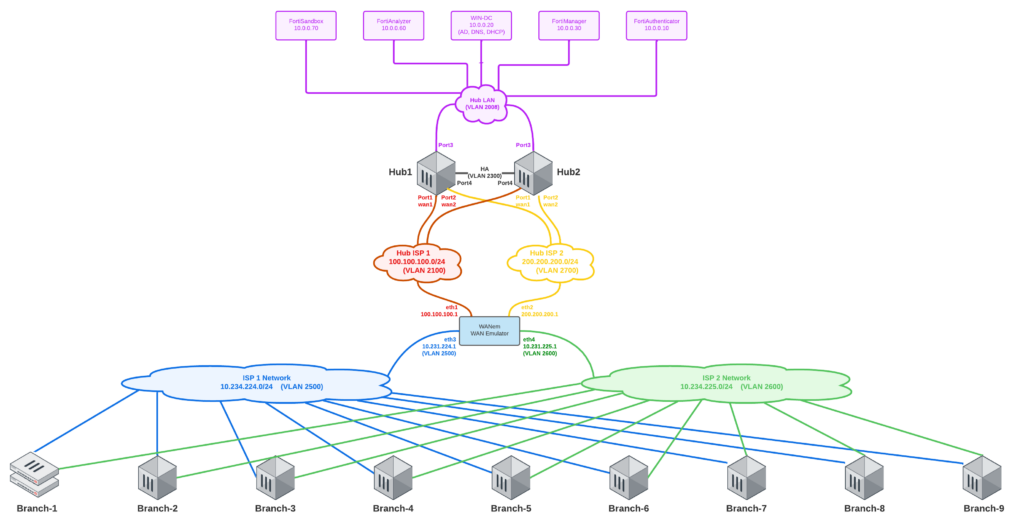
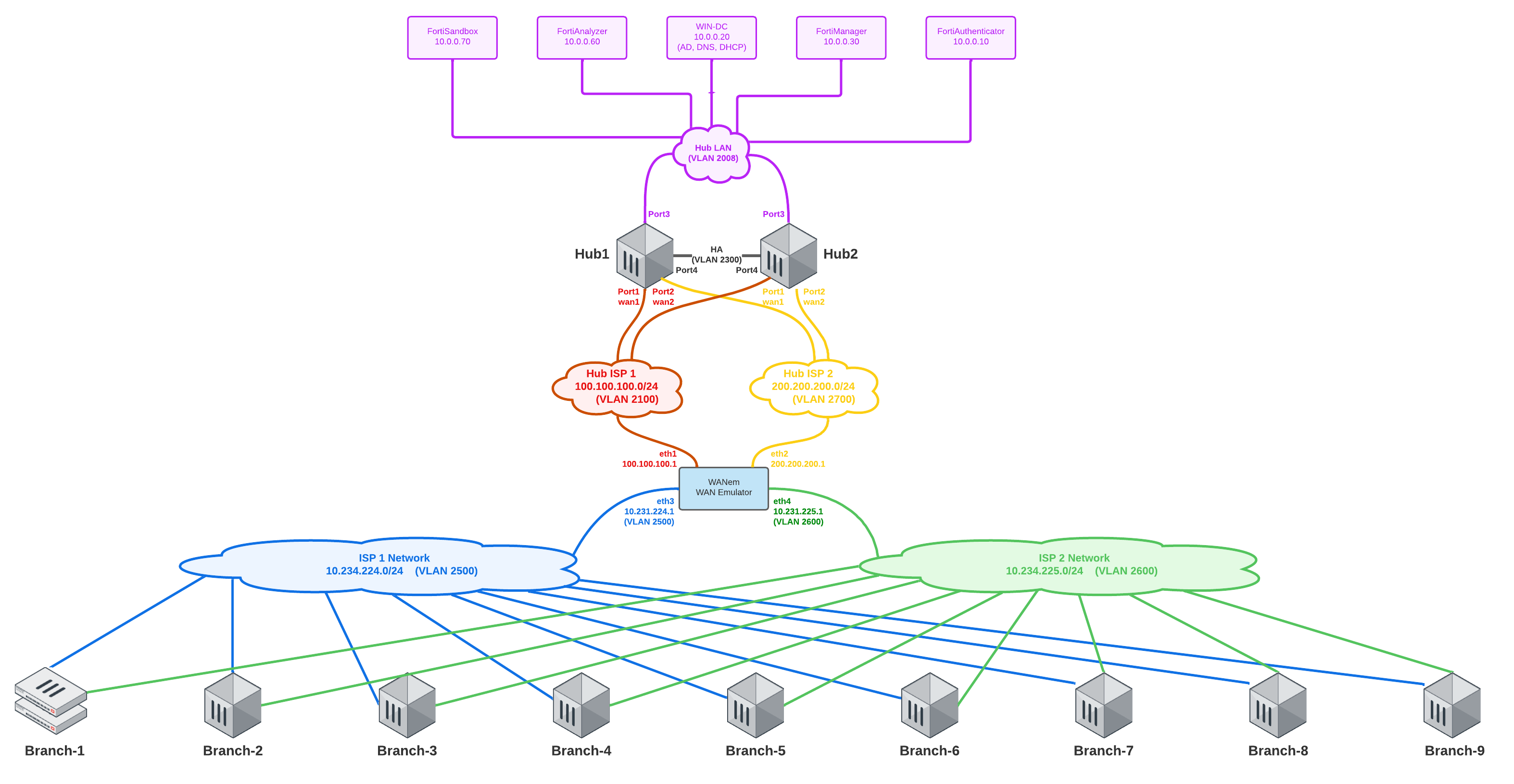
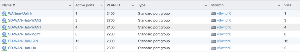
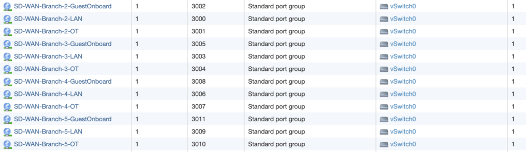
My lab uses VLANs for each of the four WAN networks: Hub WAN1 (red), Hub WAN2 (yellow), Branch WAN1 (blue) and Branch WAN2 (green). Each Branch has two WAN uplinks (through different ISPs) and three LAN downlinks. If it’s difficult to see adequate detail in the above diagram, right-click it and open in new tab so that you can see it at full resolution. These WAN and LAN networks are configured as Port Groups on VMware vSwitches:
WANem in the SD-WAN Lab Logical Diagram above is still my “Internet backbone”. If you’ve not played with WANem before, it’s a WAN Emulation tool. It’s not been updated in quite some time, so it’s an oldie but still a goodie. Rather than re-type how to deploy WANem, you can hop over to my old blog post for that section and then come back to this post. The big change from my old blog post is that I use larger subnets for Branch WAN1 and WAN2 now, since my smaller subnet masks before wouldn’t allow for as many Branches as I wanted to deploy; the new IP addressing is as follows:
- eth0 = Network Adapter 1 = Infrastructure = 192.168.5.102/24
- eth1 = Network Adapter 2 = Hub-WAN1 = 100.100.100.1 /24
- eth2 = Network Adapter 3 = Hub-WAN2 = 200.200.200.1 /24
- eth3 = Network Adapter 4 = Branch-WAN1 = 10.231.224.1 /24
- eth4 = Network Adapter 4 = Branch-WAN2 = 10.231.225.1 /24
- eth5 = Network Adapter 5 = WANem-Uplink = 192.168.99.2 /24
My Branch WAN DHCP server was also modified to use these new subnets of 10.231.224.x and 10.231.225.x; you can reference the old blog post for the ISC DHCP configuration and modify the subnets to match the new ones above (if you’re following this setup identically).
And finally in the initial setup, you’ll deploy your Hub FortiGates the same way we did in the old blog post. No big changes to the Hubs as far as networking in the lab redesign this year.
Now that our underlying framework is up and running, we can pivot to FortiManager to configure the Branches!
Metadata Variables
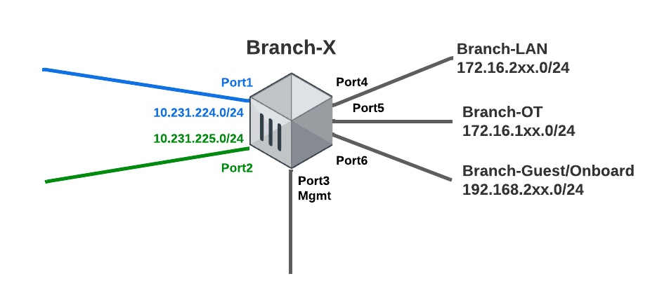
For our templates in FortiManager to make sense, I wanted to illustrate how I configured the networking for my Branch FortiGate VMs. The above diagram shows the port layout and which port maps to which network.
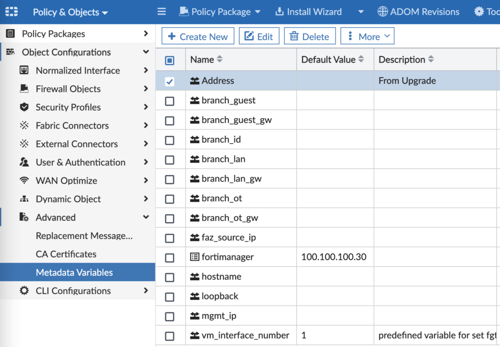
To make our design and templates scalable, we are utilizing Metadata Variables in FortiManager. A Metadata Variable is a variable that can have a different value for different devices or platforms and then be referenced in templates. It’s similar to Meta Fields (if you’re familiar with them, they’re under FMG > System Settings > Advanced > Meta Fields), but NOW in FOS 7.2 you need to use Metadata Variables under FMG > Policy & Objects > Advanced) in all your templates. For those of you migrating from FMG 7.0 to 7.2, you’ll need to manually recreate these Metadata Variables. If you’re on a fresh install of FMG 7.2, just start here under Metadata Variables and forget Meta Fields even exist. In our lab, we have the following Meta Variables:
And when you edit a Metadata Variable, you can assign a per-device value to be used in your Provisioning Templates:
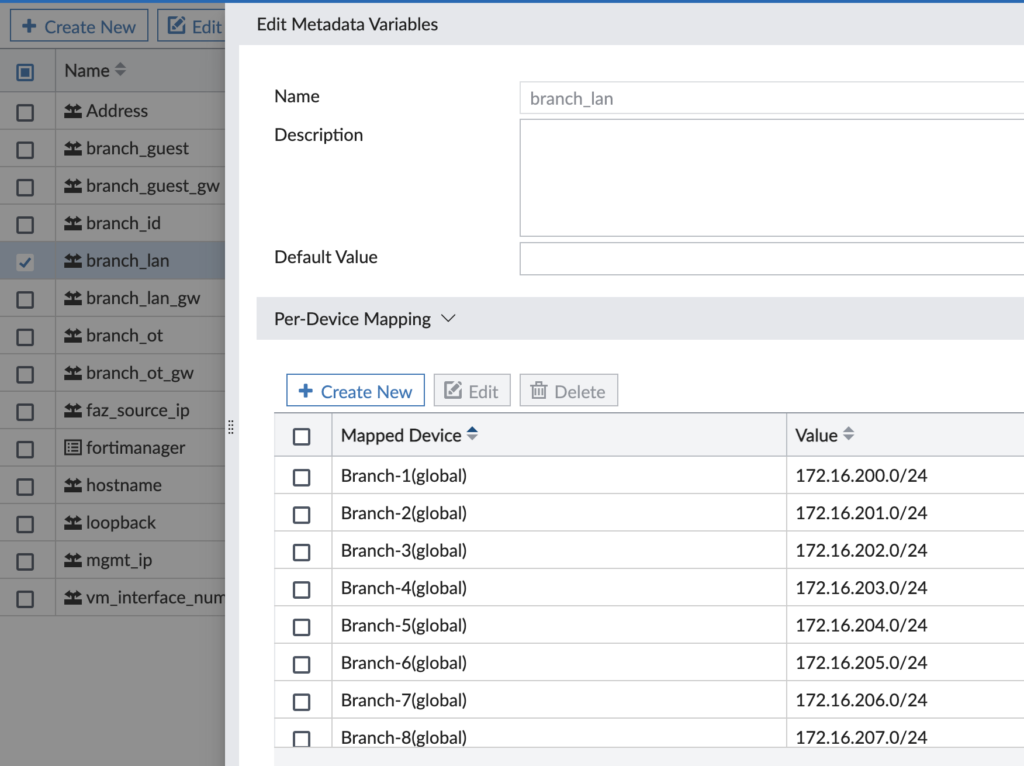
For my lab, here’s an example of the values given to a Branch device’s Metadata Variables:
- branch_guest = 192.168.254.0/24
- branch_guest_gw = 192.168.254.1/24
- branch_id = 1
- branch_lan = 172.16.200.0/24
- branch_lan_gw = 172.16.200.1/24
- branch_onboard = 192.168.254.0/24
- branch_onboard_gw = 192.168.254.1/24
- branch_ot = 172.16.100.0/24
- branch_ot_gw = 172.16.100.1/24
- hostname = Branch-1
- mgmt_ip = 192.168.5.114
- loopback = 192.168.250.201
Now let’s go to FortiManager.
FortiManager
FortiManager 7.2 added a lot more configurability to templates than existed in FOS 7.0. When I built the lab on FOS 7.0, I had to use CLI Templates to configure IPsec VPN and BGP because these sections in the Provisioning Templates just didn’t have the level of detail I needed. Thankfully the Import feature in FortiManager 7.2 allowed me to import my BGP and IPsec VPN config from my existing Branch FortiGate and save that config as a Provisioning Template. Here is how my Provisioning Templates are broken down:
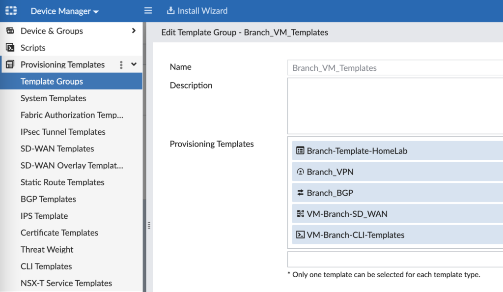
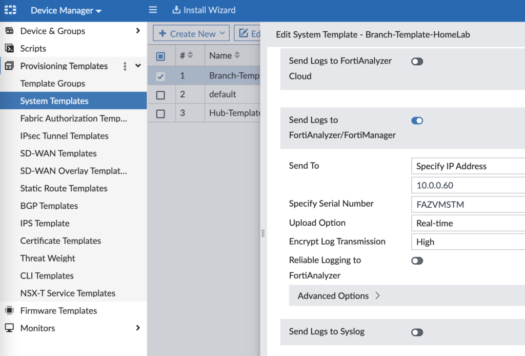
- System Templates (Branch-Template-HomeLab) – this has my SNMP and logging config
- IPsec Tunnel Templates (Branch_VPN) – this is my Hub and Spoke (with ADVPN) IPsec VPN config
- BGP Templates (Branch_BGP) – this is my BGP config to peer with the Hubs and support ADVPN
- SD-WAN Templates (VM-Branch-SD_WAN) – this is my template for SD-WAN members, rules and SLAs
- CLI Templates (VM-Branch-CLI-Templates) – this is how I configure hostname, network interfaces, etc.
System Templates
I use System Templates in my lab to configure SNMP monitoring and logging to FortiAnalyzer. You can also configure other system settings such as DNS, NTP, FortiGuard overrides, etc.
IPsec Tunnel Templates
Since my design uses redundant VPN tunnels (one over Branch WAN1 to Hub WAN1 and likewise for WAN2), I have configured two VPN interfaces for my Branch IPsec VPN template:
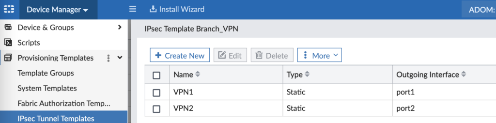
The key on this is to create as many VPN tunnels as you plan to need in your architecture and ensure the Outgoing Interface matches your WAN interfaces on your Branch FortiGates. I have two VPN tunnels in my lab: one tunnel over WAN1 and another tunnel over WAN2. Since I had different model FortiGates at branches with different WAN interfaces (i.e. some were “wan1” whereas some were “port1”), I had to use a different IPsec Tunnel Template for different FortiGate device types.
When you Create or Edit the VPN1 tunnel, you’ll use settings similar to these:
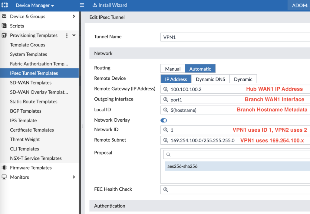
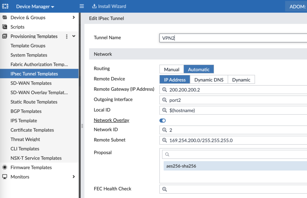
Our design uses 100.100.100.2 for Hub WAN1, 200.200.200.2 for Hub WAN2, 169.254.100.0/24 for VPN1 tunnel addressing and 169.254.200.0/24 for VPN2 tunnel addressing. Further down in the config (not shown in the screenshot), you’ll configure your Phase 2 encryption settings. Repeating the above for VPN2, you can see the pattern:
And for a sanity check, this is what the config looks like on the Branch FortiGate once applied later on:
config vpn ipsec phase1-interface
edit “VPN1”
set interface “port1”
set ike-version 2
set peertype any
set net-device enable
set mode-cfg enable
set proposal aes256-sha256
set add-route disable
set localid “Branch-1”
set comments “VPN: VPN1 [Created by IPSEC Template]”
set idle-timeout enable
set auto-discovery-receiver enable
set auto-discovery-shortcuts dependent
set network-overlay enable
set network-id 1
set remote-gw 100.100.100.2
set psksecret <preshared key>
set dpd-retrycount 2
set dpd-retryinterval 2
next
edit “VPN2”
set interface “port2”
set ike-version 2
set peertype any
set net-device enable
set mode-cfg enable
set proposal aes256-sha256
set add-route disable
set localid “Branch-1”
set comments “VPN: VPN2 [Created by IPSEC Template]”
set idle-timeout enable
set auto-discovery-receiver enable
set auto-discovery-shortcuts dependent
set network-overlay enable
set network-id 2
set remote-gw 200.200.200.2
set psksecret <preshared key>
set dpd-retrycount 2
set dpd-retryinterval 2
next
end
config vpn ipsec phase2-interface
edit “VPN1”
set phase1name “VPN1”
set proposal aes256-sha256
set auto-negotiate enable
set comments “VPN: VPN1 [Created by IPSEC Template]”
next
edit “VPN2”
set phase1name “VPN2”
set proposal aes256-sha256
set auto-negotiate enable
set comments “VPN: VPN2 [Created by IPSEC Template]”
next
end
BGP Templates
We use iBGP across the VPN tunnels for route sharing and the ability to build spoke to spoke VPN tunnel shortcuts (using Auto-Discovery VPN or ADVPN). Here is how we configure our BGP template for our Branches:
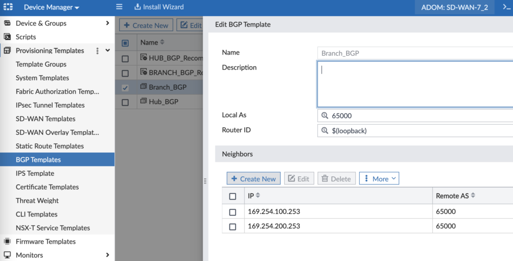
Our Hub cluster is 169.254.100.253 (via VPN1) and 169.254.200.253 (via VPN2) and we’re using the loopback IP address Metadata Variable for the Router ID. In our next screenshot we can see how we’re using the various network Metadata Variables to define our advertised networks:
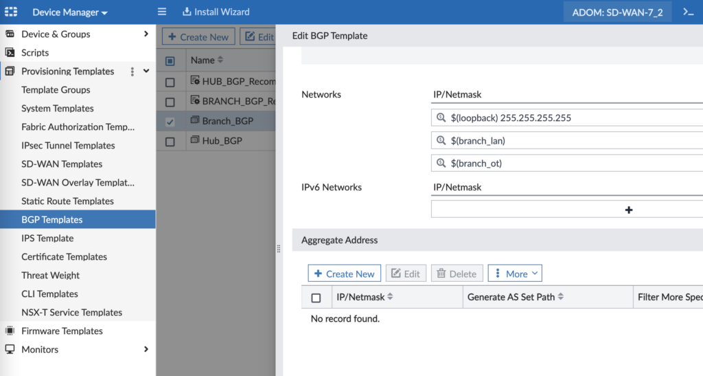
Metadata Variables are that secret sauce that allow us to templatize our BGP config, yet still keep it unique for each target device we’ll install it on. There are more BGP config settings that are important for graceful restart, multipath, etc. and I’ve captured them in the below config (also as a sanity check if your config looks different once installed on a device):
config router bgp
set as 65000
set router-id 192.168.250.201
set ibgp-multipath enable
set additional-path enable
set graceful-restart enable
set additional-path-select 4
config neighbor
edit “169.254.100.253”
set advertisement-interval 1
set capability-graceful-restart enable
set link-down-failover enable
set soft-reconfiguration enable
set description “VPN1”
set interface “VPN1”
set remote-as 65000
set route-map-out “Out-of-SLA”
set route-map-out-preferable “VPN1”
set connect-timer 1
set additional-path receive
next
edit “169.254.200.253”
set advertisement-interval 1
set capability-graceful-restart enable
set link-down-failover enable
set soft-reconfiguration enable
set description “VPN2”
set interface “VPN2”
set remote-as 65000
set route-map-out “Out-of-SLA”
set route-map-out-preferable “VPN2”
set connect-timer 1
set additional-path receive
next
end
config network
edit 1
set prefix 192.168.250.201 255.255.255.255
next
edit 2
set prefix 172.16.200.0 255.255.255.0
next
edit 3
set prefix 172.16.100.0 255.255.255.0
next
end
You may be looking at that config and wondering “what’s up with the route tags?”. Great question! But it’s too deep a rabbit hole to go down here and I promise a future blog post to explain the structure. But in a simple explanation, we map Route Tag 1 to VPN1 and we use them in our SD-WAN Rules if a member is out of SLA or not. More to come on this one though… (and as promised, here you go: https://www.andrewtravis.com/2023/02/23/fortigate-bgp-and-sd-wan/)
SD-WAN Templates
Next up is an SD-WAN Template to apply to our Branches. The beauty of this method is that if something changes (i.e. you change the IP address that one of your SD-WAN SLAs is pinging), you just change it here once and push it to all your devices.
Step 1 – Zones and Member Interfaces
For starters, you need to define your SD-WAN Zones. Think of them as a logical grouping of interfaces that can then be referenced in Firewall Security Policies. In my environment, I place both VPN interfaces in a SD-WAN Zone, but leave my WAN interfaces in separate Zones since I want them to operate independently.
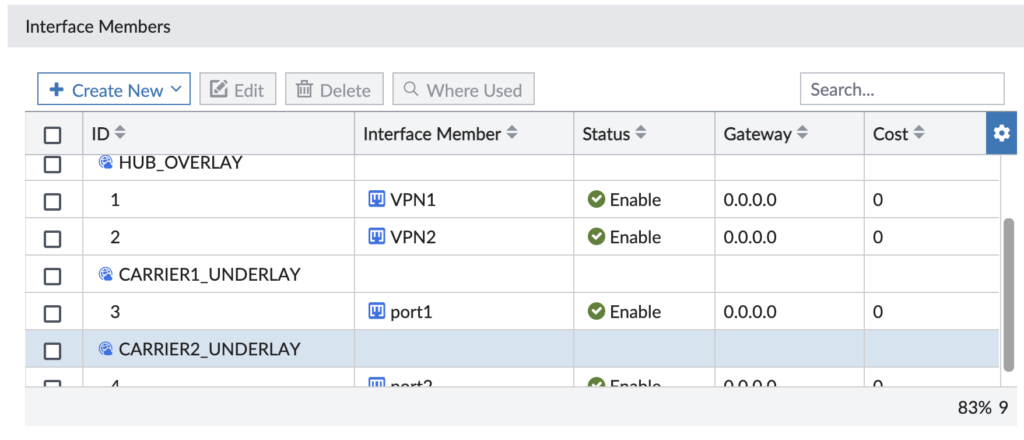
And don’t let the naming trip you up. We say Underlay for an Internet-connected interface and Overlay for VPN tunnel interfaces (that ride over those Underlay interfaces).
Step 2 – SD-WAN Performance SLAs
I have the following Performance SLAs that monitor some resource and define how many times the criteria fails before that Performance SLA is out of the desired service level agreement.
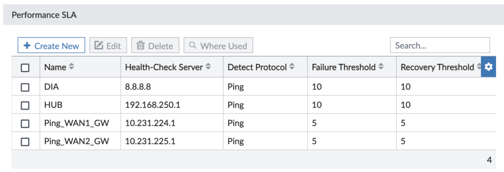
My Performance SLAs are pretty simple — they just ping different resources, though we have the option for other protocols. Here’s more detail on the Direct Internet Access (DIA) Performance SLA we use to ensure our redundant Internet uplinks are healthy and choose our preferred one:
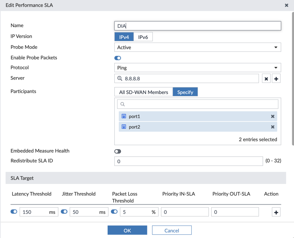
It pings the resource (i.e. 8.8.8.8) over the participating members (i.e. port1, port2) and if it has latency > 150ms or jitter > 50ms or packet loss > 5%, then it’s out of SLA. We’ll use these Performance SLAs in our SD-WAN Rules where we make traffic steering decisions based upon the Performance SLA being in SLA or out of SLA.
Step 3 – SD-WAN Rules
Now’s the time to use the previous two steps and steer some traffic! Usually you’ll define your SD-WAN rules around business applications to ensure they go the route you desire and use a backup path if the primary path falls out of SLA. In my example, my lab’s business critical applications are SAP and Microsoft 365/Teams/OneDrive so I created rules for each of them:

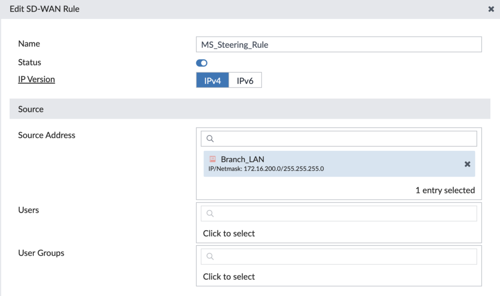
Think of a SD-WAN rule like you do a Firewall Rule: they are matched in order and the first match applies to the traffic. We’re able to tap into the FortiGate’s vast database of applications to select our desired application to steer. Let’s drill into our “MS_Steering_Rule” for Microsoft 365 traffic:
First section is defining our source to match upon — it could be an IP address, subnet, user, group, etc. We use the source subnet for our LAN subnet at the Branch:
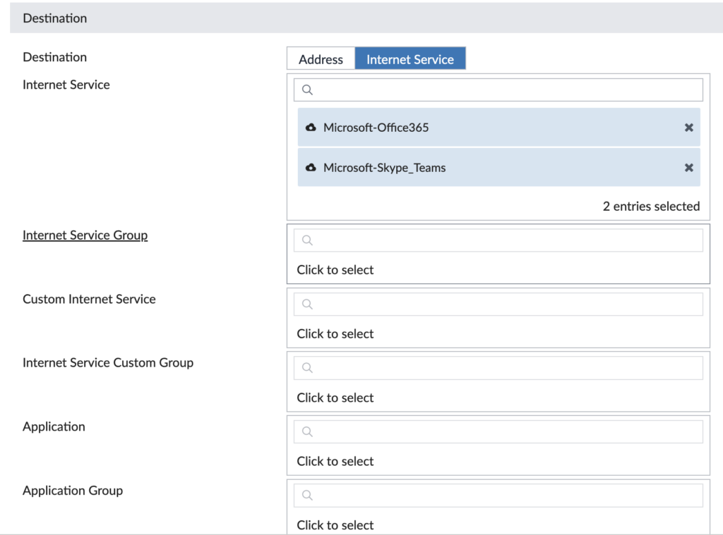
The next section is defining our destination to match upon — it could be an Internet service, application, IP address, QoS value, etc. We’re matching upon the Microsoft 365 Internet services:
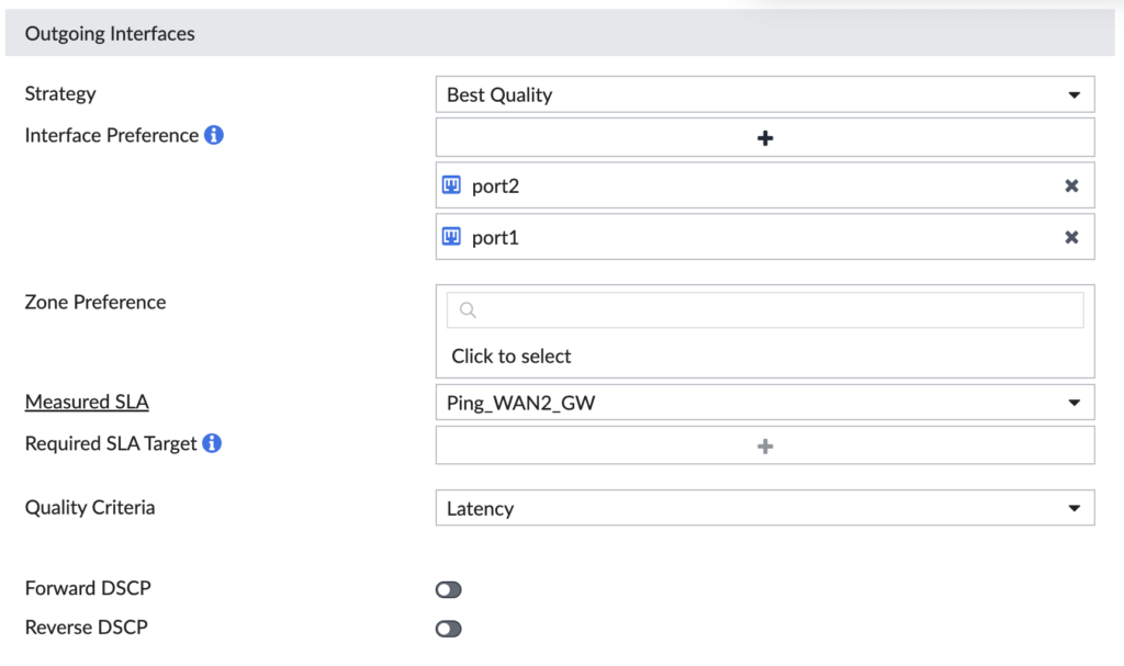
The last section is defining what interfaces we want to participate in this rule, which Performance SLA to measure health against and what strategy to use to route the traffic. In ours, we’re using both the Underlay interfaces connected to the Internet and it will prefer port2 as long as it meets our SLA (because we’ve selected port2 higher in the order than port1):
Now let’s check the same thing for our Direct Internet Access (DIA) Rule… This one matches on any destination, so it’s our last rule of the list, otherwise it would match our Microsoft traffic. This rule uses port1 for any traffic matching it.

In our design, we want Microsoft 365 traffic to use port2 (WAN2, ISP2) and all other Internet-bound traffic to use port1 (WAN1, ISP1). We’re ensuring our business critical traffic gets the “better” ISP and all our other traffic uses the other ISP. Now we don’t have to worry about generic Internet-bound traffic squashing our business critical traffic. And if the SLAs fail on either SD-WAN Rule, it’ll choose the surviving Internet uplink seamlessly. It’s a thing of beauty!
CLI Templates
CLI Templates are amazing to do all the things you want to that aren’t in the FortiManager GUI (yet). I use these templates to configure interfaces, set the FortiGate’s hostname and set many other settings.
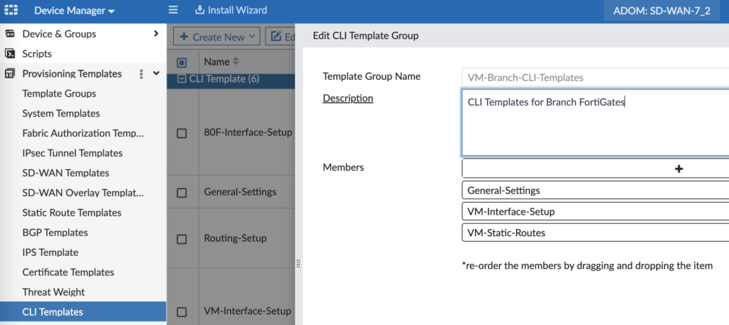
“General Settings” sets the hostname and defines our local admin password (otherwise it’s blank until you first login manually):
config system global
set hostname $(hostname)
end
config system admin
edit “admin”
set password <super secret local admin password>
next
end
Interface Setup is the quick and dirty way to create our interfaces so much faster than manually in the FortiManager GUI, per device. So much faster… Here’s the CLI config I use for my lab:
config system interface
edit “port1”
set vdom “root”
set mode dhcp
set allowaccess ping
set type physical
set alias “WAN1”
set role wan
next
edit “port2”
set vdom “root”
set mode dhcp
set allowaccess ping
set type physical
set alias “WAN2”
set role wan
next
edit “port3”
set vdom “root”
set ip $(mgmt_ip) 255.255.255.0
set allowaccess ping https ssh snmp http fgfm
set type physical
set alias “MGMT”
next
edit “port4”
set vdom “root”
set alias “Branch-LAN”
set dhcp-relay-service enable
set ip $(branch_lan_gw)
set allowaccess ping
set device-identification enable
set dhcp-relay-ip “10.0.0.20”
next
edit “port5”
set vdom “root”
set alias “Branch-OT”
set dhcp-relay-service enable
set ip $(branch_ot_gw)
set allowaccess ping
set device-identification enable
set dhcp-relay-ip “10.0.0.20”
next
edit “port6”
set vdom “root”
set alias “Branch-Guest”
set dhcp-relay-service enable
set ip $(branch_guest_gw)
set allowaccess ping
set device-identification enable
set dhcp-relay-ip “10.0.0.20”
next
edit VPN1
set allowaccess ping
next
edit VPN2
set allowaccess ping
next
edit “lo1”
set vdom “root”
set ip $(loopback) 255.255.255.255
set allowaccess ping
set type loopback
next
end
For this last one I probably could’ve created a Static Route Template in the FortiManager GUI, but I already had this config handy:
config router static
edit 10
set device “port1”
set dynamic-gateway enable
next
edit 11
set device “port2”
set dynamic-gateway enable
next
end
That wraps up all of our templates. Whew, what a long read/write up! But now we’re ready to deploy our Branches!
Branch FortiGate Deployment
In my lab, I mostly use FortiGate VMs as my Branches based upon availability, rack space, etc. so this walkthrough will begin with how to deploy the FortiGate VM in ESXi. Shortly after, we’ll dive right into configuring it in FortiManager.
Step 1 – Deploy FortiGate VM in ESXi
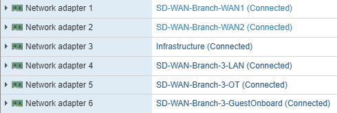
Deploy your FortiGate VM OVF without powering it on and map the interfaces similar to those I have above. I deleted NICs 7 and up since I didn’t use them, plus it makes the FortiGate interfaces look cleaner.
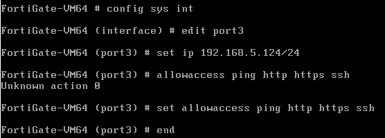
Step 2 – Power Up the VM, Address Management Interface
Now power your FortiGate VM up and give the management interface (port3 for my lab) an IP address you can reach across your network.
Step 3 – Access GUI and Upload License
Once you login as admin with no password, you’ll give the FortiGate any password (since we’ll reset it in a few steps). The only option you have now is an eval license or to upload your license downloaded from FortiCare.
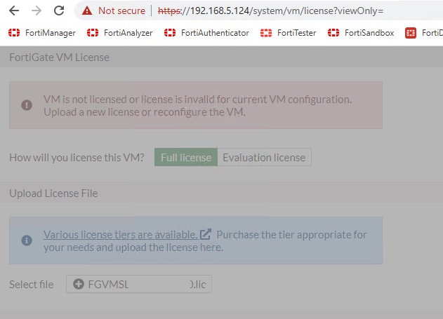
The FortiGate will reboot and once it does, go ahead and factory reset it so that we can configure it from FortiManager. The trick is running the “exec factoryreset keepvmlicense” command. Without completing this licensing step, my installation from FortiManager failed because I didn’t have entitlement to push all my config (and create all the additional interfaces) without a valid license.
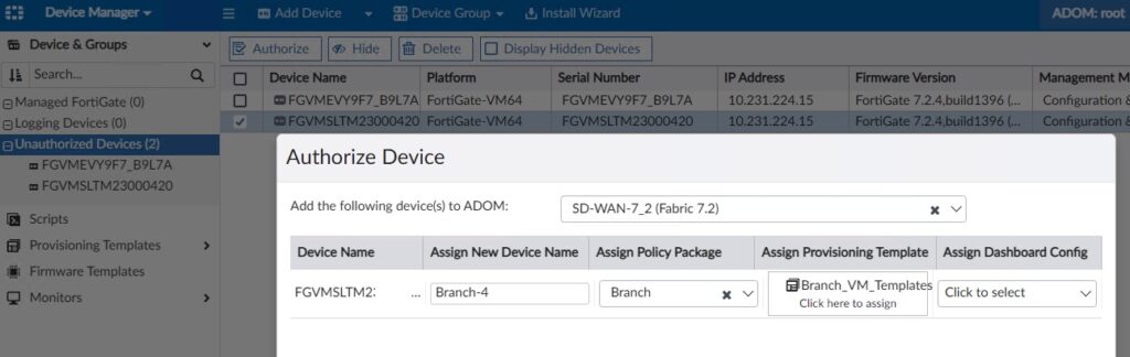
Step 4 – Authorize in FortiManager
When we deployed our WAN DHCP server, we specified DHCP option 240 with the IP address of FortiManager. And just like magic, our FortiGate VM registered itself to FortiManager so that we can configure it! Option 240 is the workaround to using FortiDeploy and works great in a lab environment. I have a separate Administrative Domain (ADOM) in FortiManager for my SD-WAN Lab and my FortiGate VM first shows up under my root ADOM. From here, I select the device, click Authorize and specify the following:
- ADOM = <destination ADOM> (if not root)
- New Device Name = Branch-X
- Policy Package = Branch (this package’s creation was outside the scope of this post, it’s already long enough!)
- Provisioning Template = Branch_VM_Templates
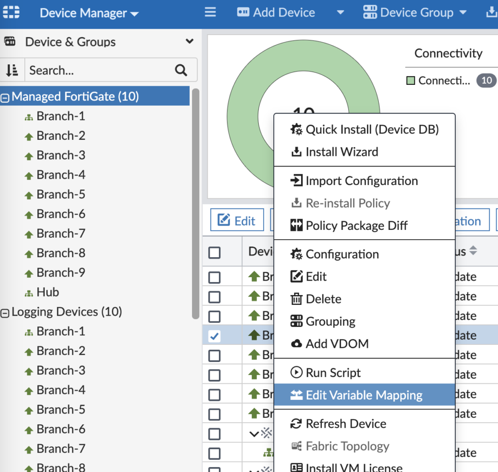
Step 5 – Set Metadata Variables
We defined what Metadata Variables are earlier and now we’re ready to assign them values. Go into the ADOM with the device > Device Manager > Right-click the device > Edit Variable Mapping.
And give them values similar to these:
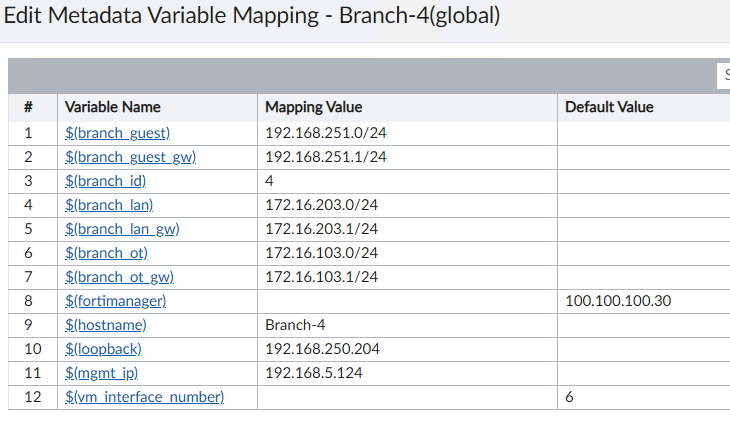
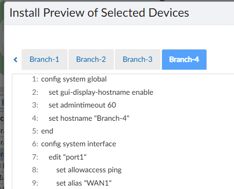
Step 6 – Install Device Settings
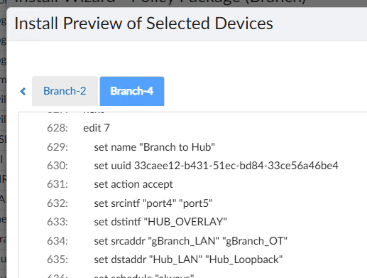
You’re now ready to install the device’s settings from FortiManager. This will basically set everything on the device besides the Policy Package. It will create interfaces, build VPN tunnels, setup BGP adjacencies, define SD-WAN rules, etc. You’ll click Install Wizard on the top blue bar in FortiManager and step through the wizard to install the updates to the Branch FortiGate. I will warn you that unless you’re perfect and don’t make mistakes (I’m not that person, trust me), you definitely want to preview the changes before installing them. When you preview, it will look like this plus another 100+ lines of config:
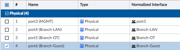
After finishing the install wizard, your Branch FortiGate is almost finished. We just need to map our interfaces to Normalized Interfaces so that our Policy Packages will install correctly.
Step 7 – Map Interfaces and Global Address Objects
Drill into your device in FortiManager > Device Manager > System > Interfaces and edit each interface to map the device’s interfaces to the Normalized Interfaces used in your Policy Packages:
And likewise, if you’re using the Global Database in FortiManager and giving objects unique values for each device, then you will want to edit each object and give it a per-device value:

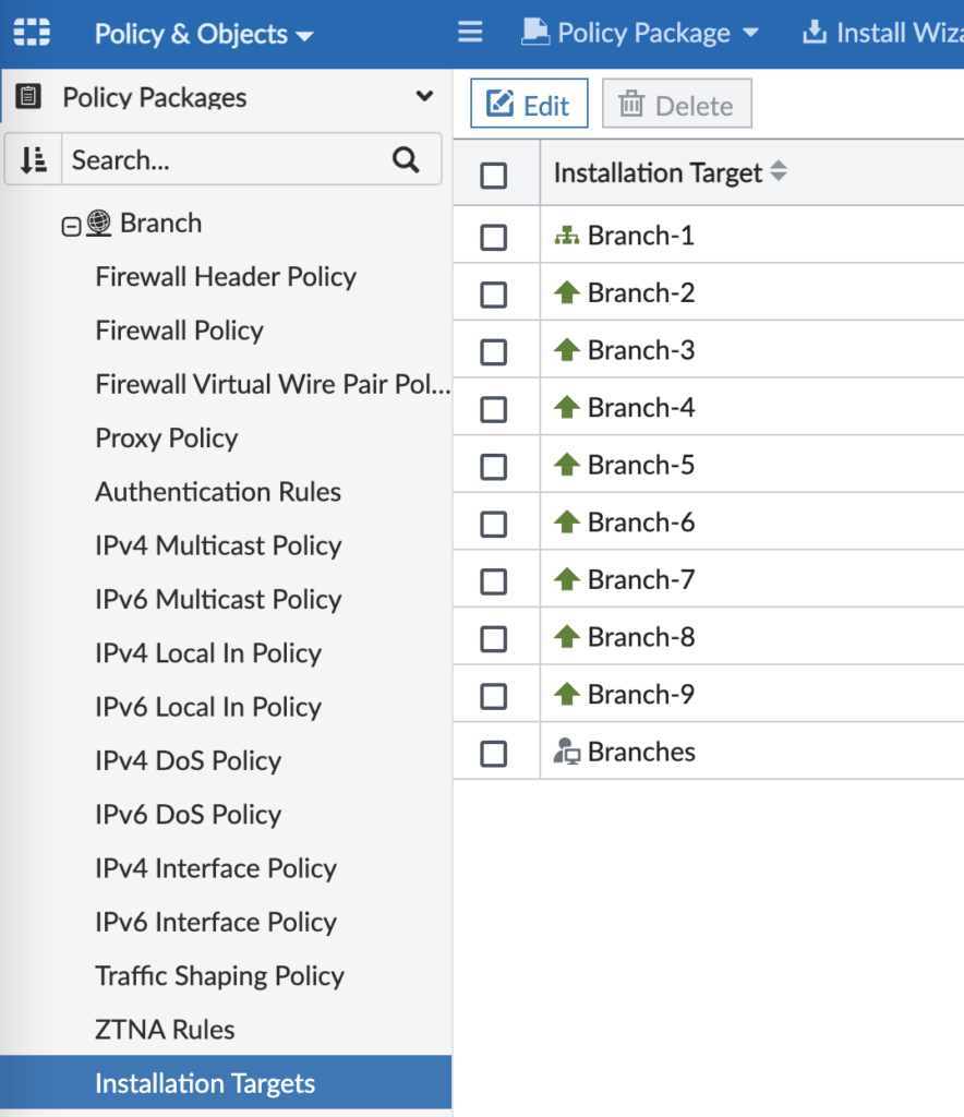
Step 8 – Install Branch Policy Package
This step assumes you already have a Policy Package with firewall rules, security profiles, etc. And it assumes that your Policy Package uses the Normalized Interfaces you mapped to in the previous step. I guess I should also say it assumes you’ve assigned your Policy Package to your target device(s) too:
In FortiManager, go to Policy & Objects and click Install on the top blue bar. As before, definitely preview the install before going through with it in case you need to tweak anything.
Viola! Your Branch FortiGate is deployed and you’re ready to rinse and repeat on the remaining Branches.
Conclusion
This was a long post! But it wrapped up a solid week of reconfiguring my lab, learning the templates in FortiManager 7.2 and realizing where I needed to adapt my FortiManager config to make it all reusable across many Branches. I hope you enjoyed reading and please comment with anything you’d like me to deeper dive into. I’ll write future posts on how we use Route Tags and SD-WAN as well as testing all this with WANem. Thanks! Andrew
Awesome work, I am in the process of studying SDWAN to pass the NSE exam, I will definitely come back here very often to go over the nice setup.
how to get lcense for tsting in the lab >
Hi Amrim, you can reach out to your Fortinet sales team for evaluation licenses — they’ll be happy to help! Andrew
Create an account to support portal,
You can download download and register your installed FMG, it will allow you to install 3 FGT
Cordially
H Andrew,
Great work.
For what purpose do you keep your wan interfaces on separate sdwan zone ?
What can’t be done if the 2 wan interfaces are in the same sdwan zone?
Thank you.
SG, great question! Having 2 WAN SD-WAN zones gives you more control on firewall policies. Primarily, if you have inbound Virtual IPs (1:1 NAT rules) then you need to map those to the specific WAN SD-WAN zone since each WAN interface would have a different IP address. But that’s the only use-case I can think of since the SD-WAN rules themselves reference the member interfaces. Please let me know if you have more questions and thanks for reading! Andrew